про Г60

CorrAnt

Corrado Nagual Rinpoche
Технический советник
Сообщения
8.159
Реакции
636
Адрес
Москва
Еще одна не совсем обычная конструкция - это спиральный, или G-образный (по форме буквы G, напоминающей спираль) нагнетатель. Идея запатентована еще в начале столетия, но из-за технических и производственных проблем на выпуск такого нагнетателя долго никто не решался. Первой, в 1985 году была фирма Volkswagen, которая применила его на двигателе купе Polo (1,3 л, 113 л. с.). В 1988 году появился более мощный нагнетатель G60, которым в течение нескольких лет комплектовались двигатели Corrado и Passat (1,8 л, 160 л. с.,), а Polo G40 выпускался вплоть до 1994 года.

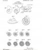
Схематично (рис. 6) конструкцию G-образного нагнетателя можно представить в виде двух спиралей, одна из которых неподвижна и является частью корпуса. Вторая - вытеснитель - расположена между витками первой и закреплена на валу с эксцентриситетом в несколько миллиметров. Вал приводится от двигателя ременной передачей с отношением около 1:2.


При вращении вала внутренняя спираль совершает колебательные движения и между неподвижной (корпус) и обегающей (вытеснитель) спиралями образуются серпообразные полости, которые движутся к центру, перемещая воздух от периферии и подавая его в двигатель под небольшим давлением. Количество перемещаемого воздуха зависит от частоты вращения коленчатого вала двигателя.

Система имеет сравнительно высокий (около 65%) КПД. Трущихся частей почти нет, поэтому износ деталей незначителен. Установленный на двигателе Polo нагнетатель G40 (40 и 60 в маркировке нагнетателей Volkswagen - это ширина спиральных камер в миллиметрах) имеет внутреннюю степень сжатия 1,0; максимальное давление наддува составляет 0,72 бар. При номинальной частоте вращения ротора 10200 об./мин. за один оборот подается 566 см куб. воздуха, т. е. почти 6000 л/мин.

Схема управления механическим нагнетателем довольно проста (рис. 7). При полной нагрузке заслонка перепускного трубопровода закрыта, а дроссельная открыта - весь поток воздуха поступает в двигатель. При работе с частичной нагрузкой дроссельная заслонка закрывается, а заслонка трубопровода открывается - избыток воздуха возвращается на вход нагнетателя.


Входящий в схему охладитель наддувочного воздуха (Intercooler) является почти непременной составной частью всех, не только механических, систем наддува. При сжимании воздух, как известно, нагревается, а его плотность и, соответственно, количество кислорода в единице объема уменьшаются. Больше кислорода - лучше сгорание и выше мощность. Поэтому перед подачей в двигатель сжатый нагнетателем воздух проходит через охладитель, где его температура снижается.

Преимущества спирального нагнетателя, как и большинства компрессоров с механическим приводом: достаточно большой крутящий момент и повышенная мощность двигателя при низких оборотах, быстрая, практически мгновенная реакция на нажатие педали газа. Недостатки: относительная сложность и нетехнологичность конструкции, большие потери в приводе.


http://www.nadduv.ru/turbo.html


интересно--про производительность за оборот наврали или нет? чуть больше поллитра.... --этт к вопросу сравнения с М62 ;-)

осталось найти данные по дельта Т по Г60
 

Вложения

Последнее редактирование:

Hellraiser-Rostov

Почётный пилот
Сообщения
2.970
Реакции
51
Антон..есть карта к-ки,но что-то не прикрепляет картинку:shocked: да,ещё..обьём подачи 888см,макс степень сжатия 1.8 частота вращения 10020об-мин..это что касаеться г-ки
 

CorrAnt

Corrado Nagual Rinpoche
Технический советник
Сообщения
8.159
Реакции
636
Адрес
Москва
это что значит

Hellraiser-Rostov написал(а):
Антон..есть карта к-ки,но что-то не прикрепляет картинку:shocked: да,ещё..обьём подачи 888см,макс степень сжатия 1.8 частота вращения 10020об-мин..это что касаеться г-ки
в статье про Г40...
а у тебя данные про производительность и картинку откуда?
картинку можно corrant@mail/////////////////////////ru кинуть...
 
Последнее редактирование:

Nomid_G40

Зритель
Сообщения
367
Реакции
0
Антон у тебя в статье производительность Г40 566куб.см, если Г40 в 1.5 раза меньше чем Г60( судя по ширине лопастей), то Г60 получается 566*1,5=849см.куб :)
 

CorrAnt

Corrado Nagual Rinpoche
Технический советник
Сообщения
8.159
Реакции
636
Адрес
Москва
Текст Патента часть 1

LEON CREUX, OF PARIS, FRANCE.
ROTARY ENGINE.
No. 801,182. Specification of Letters Patent.
Application filed June 26, 1905, Serial Ho, 267,09r Patented Oct. 3, 1905.
To all whom it may
Be it known that I, LEON CEEUX, engineer,
a citizen of the Republic of France, residing
at 54 Rue Taitbout, Paris, in the Republic of
5 France, have invented certain new and useful
Improvements in Rotary Engines, of which
the following is a specification.
The present invention relates to a rotary engine
designed to be operated by an elastic fluid
10 under pressure. The said engine may of
course be used also as a pump for compressing
an elastic fluid. The said engine comprises,
essentially, between two parallel plates two
spiral strips or bands having the shape of de-
15 veloped arcs of circles of the same pitch, the
coils of which are engaged one in another and
touch at a certain number of points, so as to
form between the said bands and the said
plates a certain number of separate chambers
20 which become greater as the said points of contact
are displaced from the starting-point of
the said developed arcs of circles toward the
ends of the same. The said displacement of
the points of contact, which involves a cir-
25 cular movement of translation of one of the
spiral bands with respect to the other, is produced
naturally by the expansion of the elastic
fluid inclosed in the chambers, the said fluid
being introduced at the center of the spirals
30 and escaping at the periphery.
In the accompanying drawings, which show
several embodiments of the present invention,.
Figures 1 to 13 are diagrams for the purpose
of explaining the invention. Fig. 14 is a ver-
35 tical section of the engine on the line A A of
Fig. 15. Fig. 15 is a sectional view on the
line B B of Fig. 14. Fig. 16 is a sectional
view on the line C C of Fig. 15. Fig. 17 is
a detail of a joint. Figs. 18 and 19 are re-
40 spectively a vertical section and a plan of a
shifting device as to the direction of rotation.
Figs. 20, 21, and 22 show modified forms of
the engine.
The developed arc of a circle is the curve
45 described by the end a, Fig. 1, of an inex-
tensible wire which unrolls from a fixed circumference
while still remaining stretched
and without moving out of the plane of the
circumference. A point 5 on the wire, Fig.
50 2, at a distance c from a describes a developed
arc of a circle equal to the first one and
of which each point is at a distance c from the
first curve. If two perpendicular lines a' c?
and V V\ Fig. 3, drawn from a plane p' are so moved as to describe curves, they give rise to 55 two curved surfaces. The space comprised between the said curved surfaces and the planes p' and pz constitutes a spiral band. Such a band secured to a circular plate p', as seen in perspective in Fig. 4, constitutes one . 60 of the essential members of the engine. A similar band secured to the plate pz constitutes the other member of the engine. If the two spiral bands 1 and 2 are engaged one within the other, as shown in Fig. 5, each 65 coil of the band 1 is tangent at two points to the corresponding coil of the band 2. If a movement of translation is imparted to the band 1 with respect to the band 2, in keeping the said bands in the same direction, one 7° with respect to the other, so that the curved surfaces still remain tangent the one to the other, each point of the band 1 will describe a circumference. The spaces d e e\ &c. , are entirely inclosed, 75 and if the circular movement of translation takes place in the direction shown by the arrow the said spaces increase in size during the operation. If steam is introduced at d and if the bands 80 1 and 2 are caused to move as just described, the expansive power of the steam will produce the relative movement of the bands in the direction shown by the arrow. The steam will occupy successively the spaces shaded in 85 Figs. 6 to 13. Figs. 6 to 9 show the several phases during the first revolution. Figs. 10 to 13 show those of the second revolution. The steam will always operate at full pressure in the central chamber d and will expand 9° at each revolution in the lateral chambers e tf and will escape at/. The oblique'hatchings in Figs. 6 to 13 show the steam a-t full pressure. The vertical or horizontal hatchings show the steam when expanding, and the dot- 95 ted hatchings show the steam escaping. To cause the spiral bands to move suitably one with respect to the other, all that need be done, as will be understood, is to connect the same by a suitable number of equal and par- i°o allel cranks or other similar connecting devices. According to the manner in which the bands or their connecting members are connected with the main frame of the engine, one of the bands may be fixed, or circular move- I05 ments of translation may be imparted to both the bands, or a general or other movement of rotation may be imparted to the two bands
 

Вложения

Последнее редактирование:

CorrAnt

Corrado Nagual Rinpoche
Технический советник
Сообщения
8.159
Реакции
636
Адрес
Москва
Текст патента, часть 2

801,182
taken together independently of the relative
circular movement of translation which takes
place between the bands.
I will first describe a steam-engine in
5 which there may be secured to the main frame
BOW a point of the bands themselves and then
a point of their connecting members, so that
a change in the direction of rotation may be
obtained.
10 1 and 2 designate spiral bands which are integral
with the plates 3 and 4, respectively.
Through the plates passes a bent shaft 5, having
two cranks 6 7 at one hundred and eighty
degrees. The center of the plate 3 is mounted
15 on the crank 6 by means of a stuffing-box 8,
and the center of plate 4 is mounted on the
crank 7 by means of a stuffing-box 9. On the
other hand, the plates carry extensions 10 11,
through which pass bent shafts 12, mounted
20 in a frame 13. The latter is carried by the
sleeves 14 15, loosely mounted on the shaft 5
and which rest in the bearings 16 17 of the
main frame, so as to revolve therein. If the
frame is rendered motionless — say by the ap-
25 plication of a brake on the pulley 18, carried
by the sleeve 14 — the axes of the shafts 12 are
fixed, so that the cranks 19 20 of the said
shafts, connected, respectively, with the plates
3 4, only allow each of the latter to make a
30 circular movement of translation the radius
of which is equal to the radius of the cranks
6 and 7. In order that the guiding of the
plates may not be interfered with by the passage
at the dead-points, the shafts 12 are pro-
35 vided with other cranks 22 23, directed at
right angles to the cranks 19 20 and connected
together by lateral links or rods 24 25. If,
on the other hand, by braking the pulley 26
of the shaft 5 the latter is rendered motion-
40 less, together with the cranks 6 and 7, and if
at the same time the pulley 18 is set free, the
plates 3 4 and the frame 13 are still capable
of rotating, and during this general movement
of rotation the relative circular movement of
45 translation of the two plates and bands will
still take place.
To allow of steam being' introduced into the
central chamber of the engine, the shaft 5 is
provided with a duct 27, the shaft terminat-
50 ing in a stuffing-box 28, which is connected
to a suitable source of steam. The steam after
flowing through the coils and escaping at /
is exhausted into an annular chamber 29,
connected by conducts 30 with an exhaust-
5 5 pipe 31, provided across the main frame. The
said conducts 30, which terminate in the sleeve
15, must allow the plate 4 to move. For that
purpose they may be provided with either
jointing or telescopic parts or, as shown in
60 the drawings, with a nozzle 32, sliding against
the plate 4 in the same manner as a drawer
having a circular movement.
The joints between the lateral edges of the
bands 1 and 2 and the plates 4 and 3 and between the lateral edges of the circular casings 65 29 may be rendered steam-tight by means of suitable means — such, for instance, as segments 33, inserted in grooves in the said edges and pressed by springs 34. (See Fig. 17.) The said, segments may be provided in their 70 lateral faces with one or several stuffing- grooves 46. The joints between the curved surfaces of the bands are easily rendered steam-tight by polishing, the contacts between the same being comparatively wide. 75 As mentioned above, cither the pulley 18 or the pulley 26 may be braked at will to render motionless the frame 13 or the shaft 5. In the former case the pulley 26 rotates in the direction of the arrow D, Fig. 14; in the 80 latter case the pulley 18 rotates in the direction of the arrow E. The transmission of power will be obtained by means of a belt which can be brought alternatively on the pulleys 18 and 26. The direction of rotation 85 may also be changed by means of other suitable devices — such, for instance, as that shown in Figs. 18 and 19. The sleeve 35 may be put -in connection either with the shaft 5 or with the socket -14 by means of a piece com- 90 posed of a ring 36, sliding on the socket 14, and of two branch parts 37, sliding in the rectilinear grooves 38, provided on the inner side of the sleeve 35. Each of the said branch parts carries a spur 39, sliding in the spiral 95 grooves 40 and 45 of the shafts 5 and 14. In the position shown in Fig. 18 if the socket 14 rotates in the direction of the arrow F the sleeve 35 rotates in the same direction, the shaft 5 remaining motionless. I0° To change the direction of rotation of the engine, the incoming steam is shut off and- the piece 36 is moved forward in the direction of the arrow GK The spurs 39, sliding in the rectilinear grooves 45 and then coining in I05 contact with the shaft 5, become engaged in the spiral grooves 40, which terminate in a rectilinear part 41. A shock is thus avoided which the system of mechanism would not be capable of resisting, and the shaft 5 takes TI° gradually the same speed as the sleeve 35. Then all that need be done is -to rentier the socket 14 motionless and to turn the steam slowly on again. To change the rotation in the opposite direction, a shifting piece 42 will II5 cause the spur 39 to follow the rectilinear groove 38 by closing the entrance of the spiral groove 40. When the spur will be in contact with the socket 14, it will become engaged in the spiral groove 40 and will then operate in I2° the same manner as previously. In case the change in the direction of rotation is not necessary the engine may be arranged as shown in Fig. 20— that is, the frame 13 may be secured to the main frame of the I25 machine. The engine may also be so arranged that the axes shall be vertical, as shown in Fig.

801,182
21. One of the plates — say plate 3 — together
with the spiral band, will then be secured to
the main frame 43, and the other plate 4 is
movable on plate 3 and guided by the cranks
5 20. The bent shaft 5 is held in an upright position
by a cross-bar 44, secured to the main
frame.
As will be understood, the construction may
be modified in many ways. It may again be
10 modified in combining two or more pairs of
spiral bands. For instance, in Fig. 22 the
engine comprises two pairs of spiral bands 1
2 and la 2a. The bands 1 and la are secured
on the lateral plates 3 and 3a, and the bands
152 and 2a are secured on the middle plate 4.
The cranks 6 and 6", which carry the plates 1
and la, are in front one of the other, and the
crank T, which carries the plate 4, is diametrically
opposed to the same with respect to
20 the axis of shaft 5. The plates are guided
and the engine operates in the same manner
as hereinbefore described with reference to
Figs. 14 to 16.
In all the embodiments of the present in-
25 ventipn, as herein shown and described, the
rotation of the engine is obtained by the continuous
admission of a motive fluid, and the
expansion of the latter is as complete as may
be desired, the motive effort is regular, the
3° operation is soft and silent, and the engine can
be started under a load.
I claim —
1. A rotary engine comprising two parallel -
plates two spiral bands located between the -
35 plates and engaged the one in the other and
guiding means to cause one of the bands to make a circular movement of translation with respect to the other band. 2. A rotary engine comprising two parallel plates, two spiral bands engaged the one in 4° the other and integral with the two plates respectively, and guiding means to cause one of the bands or one of the plates to make a circular movement of translation with respect to the other band or the other plate. 45 3. A rotary engine comprising two parallel plates two spiral bands between the said plates and engaged the one in the other, guiding means to cause one of the bands to make a circular movement of translation with re- 5° spect to the other band, and a duct or conduit to conduct the incoming motive fluid under pressure to the center of the said spiral bands. 4. A rotary engine comprising a bent shaft having two opposite cranks, two parallel 55 plates loosely mounted on the said cranks a frame loosely mounted on the shaft, cranks to connect the plates with the frame in causing the same to make a circular movement of translation with respect to the said frame, 60 spiral bands integral with the said plates and engaged the one in the other, and means to render motionless at will either the said shaft or the said frame. In testimony that I claim the foregoing as 65 my invention I have signed my name in presence of two subscribing witnesses. LEON CREUX. Witnesses: HANSON C. COXE, MAURICE EOTJX.
 

CorrAnt

Corrado Nagual Rinpoche
Технический советник
Сообщения
8.159
Реакции
636
Адрес
Москва
--абратите внимание на то, что имеются отличия того, что было запатентовано и того, что сделал Фольксваген. Например изначально предусматривалось два стабилизирующих вала ;-)
 

САМ

Помощник Механика
Сообщения
473
Реакции
60
Корант,дружище,вот кое-чё по Г-ладеру,если интересно,конечно:


Слушай,ч-то скан не видать не финты,я тебе на почту кину.Мож пригодится.
Там вроде предпоследняя карта лисхольм,а последняя SC14,он же Ванкель и Огура.
 

CorrAnt

Corrado Nagual Rinpoche
Технический советник
Сообщения
8.159
Реакции
636
Адрес
Москва
САМ,
Респект и уважуха!!!!

ты попробуй их выкладывать по одной странице--тогда тут будет видно.
 

САМ

Помощник Механика
Сообщения
473
Реакции
60
Это была у меня книжка,чё-то типа:"Компрессоры.Справочное пособие" или как-то так,но её заирали давно,не помню даже кито.Остались не очень качественные сканы нескольких страчничек.Штут 20,в основном так,краткие сведения по большинству компрессоров,их плюсы и минусы и карты на некоторые.Если надо могу куда-нибудь пульнуть,там правда сборная солянка,но разобраться можно.
 
Сверху Снизу